Group Assignment 6: Electronics Design
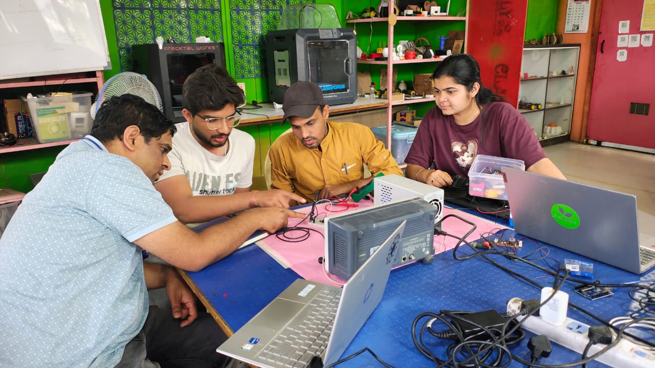
This week, we learned about basic electronic components and how they work in embedded systems. We focused on resistors, capacitors, LEDs, and microcontrollers. We also learned to use different tools in our lab. First, we looked at the tools, including the digital multimeter, variable power supply, and oscilloscope. We learned what they do and how they help us test electronic circuits.
Group Assignment Objectives:
Learn how to use lab test equipment, including a Digital Multimeter, Variable Power Supply, and Oscilloscope. These tools help you measure and analyze electronic circuits effectively.
Digital Multimeter
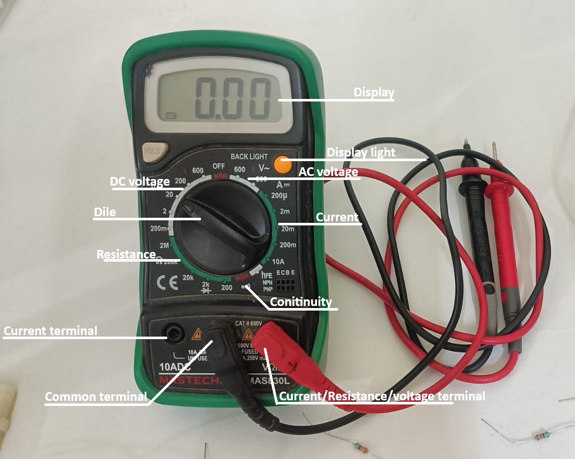
When working with electronics, the best and most important tool is a multimeter. A multimeter is used to measure different electrical parameters such as voltage, current, resistance, and continuity. It helps us check whether a circuit is working properly or not.
In our lab, two different types of multimeters are available, but we used the MASTECH MAS830L digital multimeter for our testing. This multimeter has different measurement modes. It can measure resistance from 200 ohms up to 2 mega ohms. It can measure DC voltage from 200 millivolts to 600 volts, and AC voltage from 200 volts to 600 volts. It also measures current from 200 milliampere up to 10 ampere.
We used the continuity mode to check broken wires and PCB connections. We also tested LEDs using the multimeter to verify whether they were working correctly. This tool helped us understand and troubleshoot electronic circuits safely and effectively.
Multimeter Specification
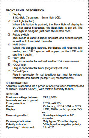
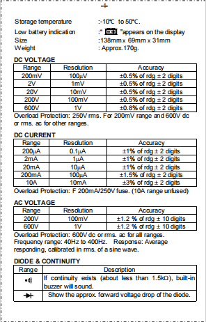
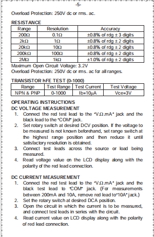
Source MASTECH MAS830L Datasheet
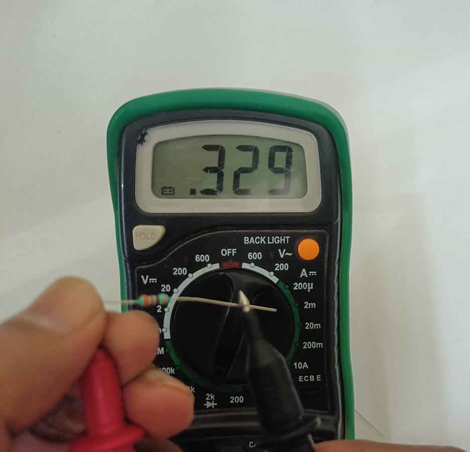
First, we tested the resistor value using a digital multimeter.
After setting the dial, we placed the red and black probes on both terminals of the resistor. The multimeter display showed the resistance value in ohms.
Before testing, we rotated the multimeter dial to the resistance (Ω) mode. Selecting the correct resistance range is important to get an accurate reading.
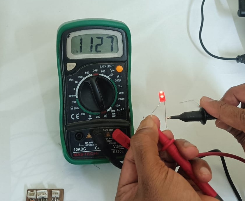
Second, we tested the LED using the multimeter.
First, we turned the multimeter dial to the continuity (or diode) mode. Then we connected the positive (red) probe to the long leg of the LED and the negative (black) probe to the short leg.
If the LED glowed slightly, it means the LED is working properly. If the LED did not light up, it means the LED may be faulty or connected in the wrong direction. This test helped us quickly check whether the LED was good or damaged.
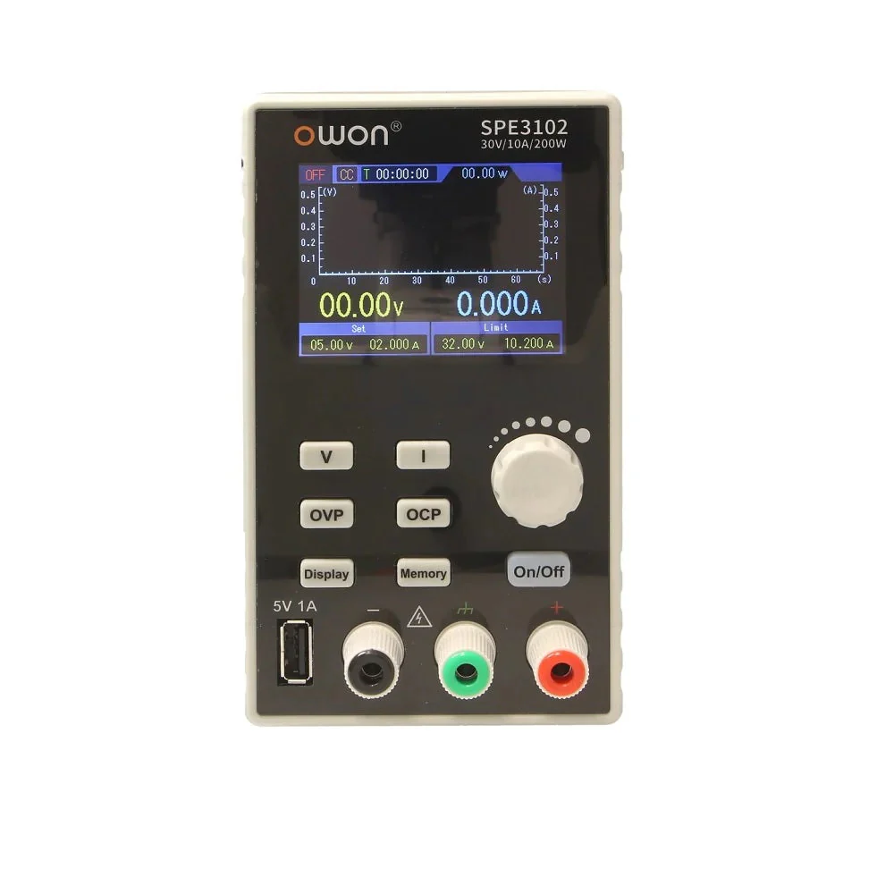
Variable Power Supply
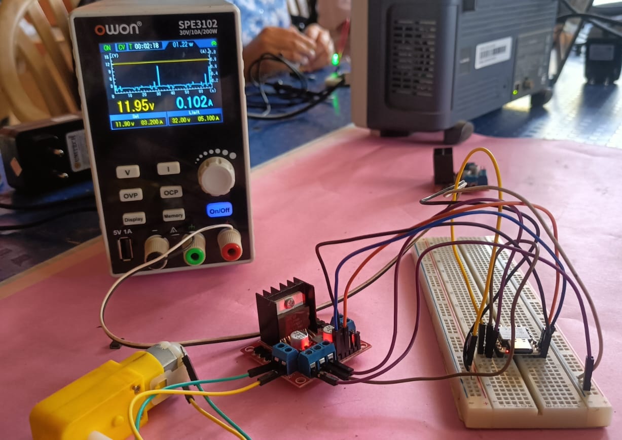
In our lab, we have an OWON SPE3102 30V 10A 200W variable power supply. This power supply comes with an OLED display. On the display, it shows a graph of current and voltage, and we can also set the voltage and current as needed.
Variable Power Supply Specification
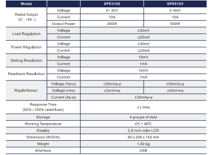
OWON SPE3102 Power Supply Datasheet
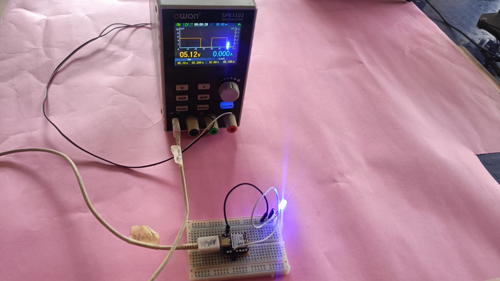
Third, we use variable power supply For powering the circuit,
we used a variable power supply. In this setup, we used a C3 microcontroller board and connected an LED to it. After uploading the program, the LED turned on.
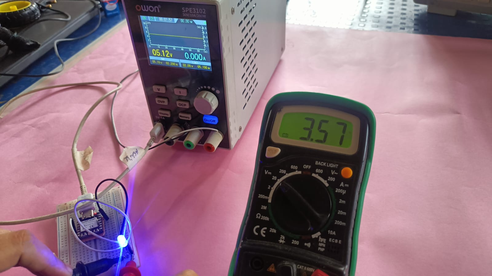
Fourth, we tested the voltage using a multimeter
then measured the voltage across the circuit using the multimeter to confirm that the board was receiving the correct power.
Fifth, we used the multimeter to measure the current of the LED in the same circuit. We set the multimeter to DC current mode and connected it in series with the LED.
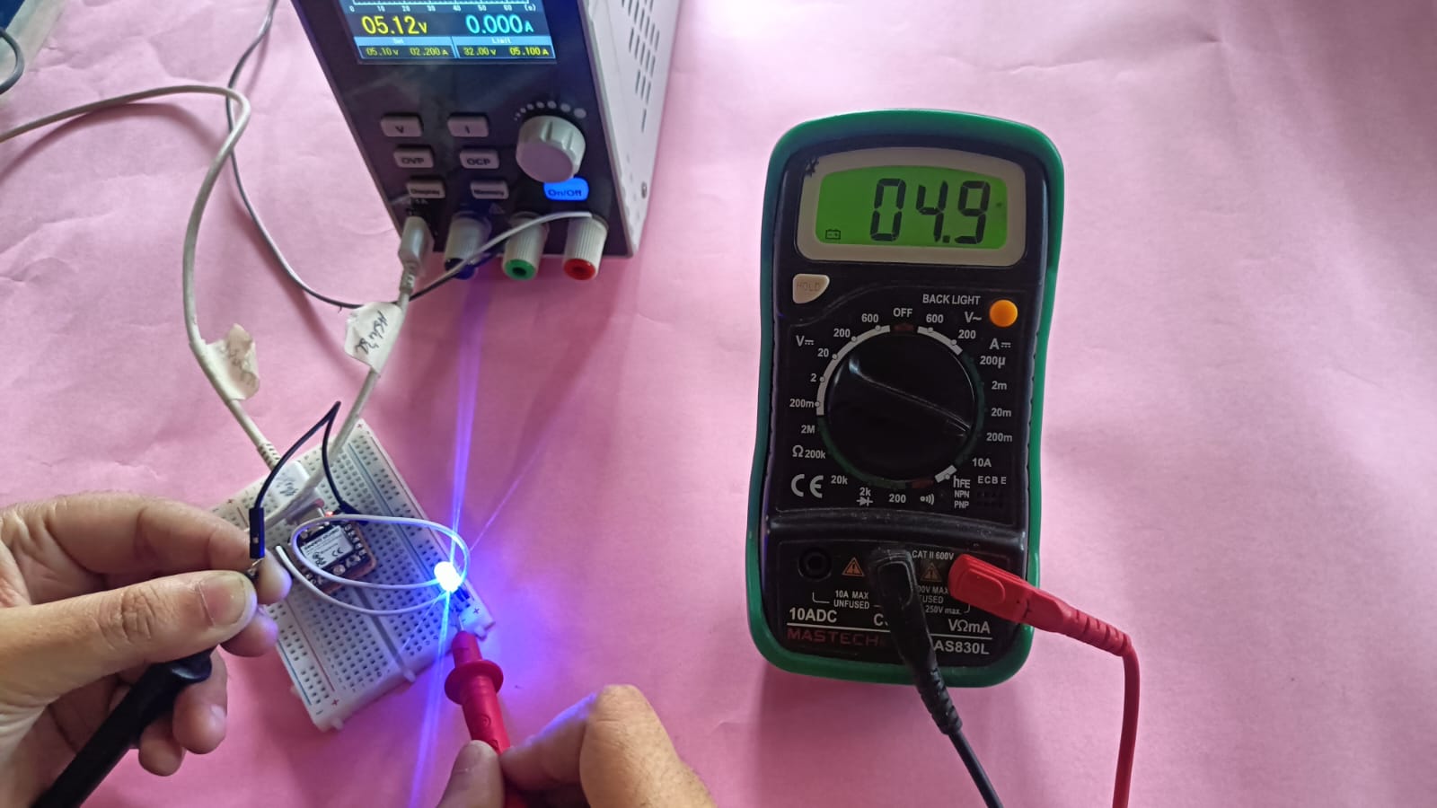
After that, we calculated the power consumption of the LED using the formula:
P = V × I = 3.57 V × 0.0047 A = 0.0168 W
This means the LED consumes approximately 16.8 milliwatts of power in the circuit.
Digital oscilloscope
Finally, we used a digital oscilloscope in our lab. The oscilloscope is a very powerful tool in electronics for observing signals in a circuit. It helps us see digital waves like square waves and also analog signals like sine waves on the display screen.
We connected the probe to our circuit and observed the signal coming from the microcontroller. The oscilloscope also helped us check if there was any noise or disturbance in the signal. By using this tool, we could clearly understand how the signal behaves in real time and verify that our circuit was working properly.
In our lab, we use the Siglent SDS 1202X-E digital oscilloscope, which offers a 200 MHz bandwidth and two input channels. It enables us to clearly observe digital and analog waveforms and measure frequency, voltage, time period, and noise in electronic circuits.
Digital oscilloscope Specification
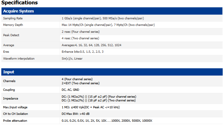
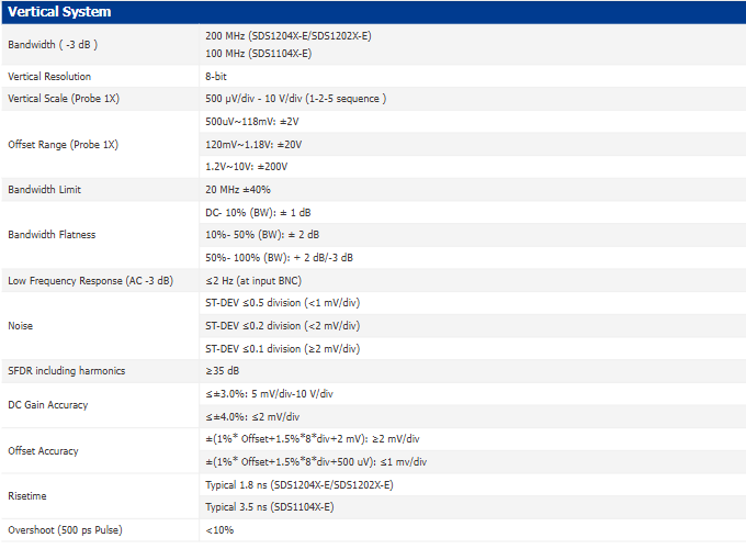
Siglent SDS1202X-E Oscilloscope Datasheet
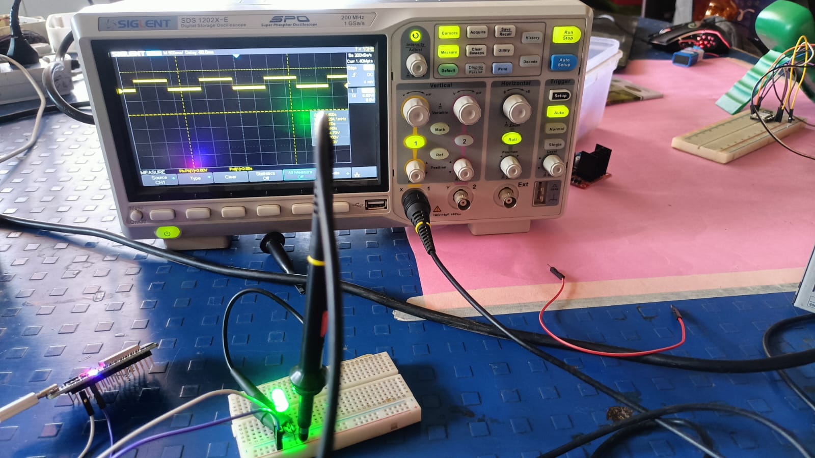
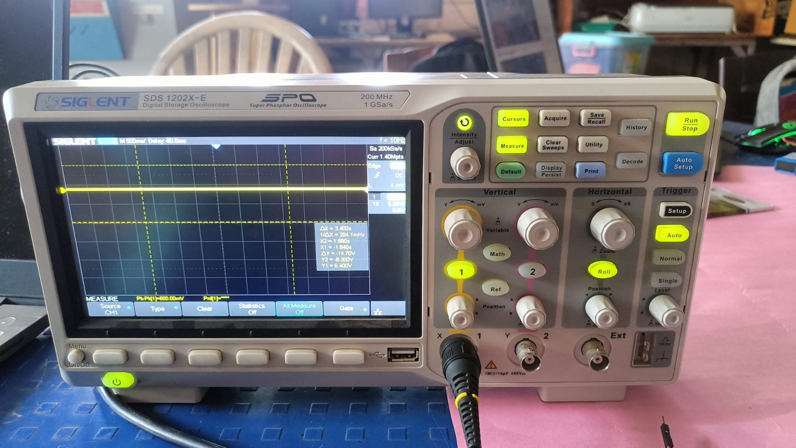
We used the XIAO ESP32 C3 module and uploaded a blink code to it. The purpose of this test was to generate a square wave signal from the output pin.
We then connected the oscilloscope probe to that pin to observe how the waveform appears on the screen. On the oscilloscope display,
we saw a clear square wave pattern, which confirmed that the microcontroller was switching between HIGH and LOW states correctly. BUt showing some noise.
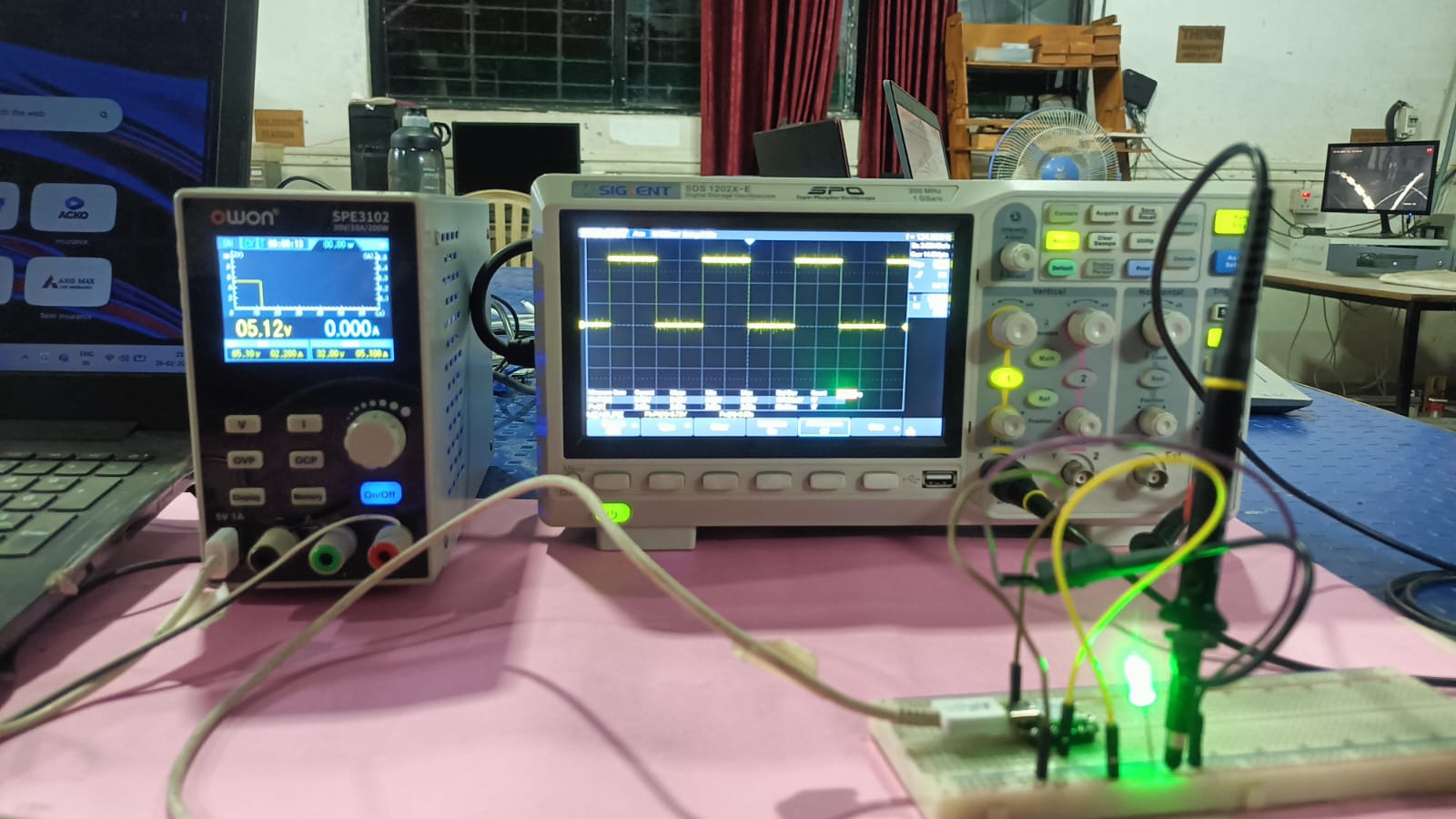
After that, we used the ESP32 module with the same blink code and observed the signal on the oscilloscope. The waveform was not completely clean, and some noise was visible in the signal.
The noise was created because we placed the ESP32 on a breadboard. Due to loose connections and longer wires, the signal was not clean. When we tested the ESP32 without the breadboard, the waveform became much clearer and more stable.